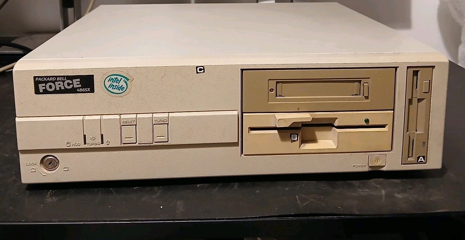
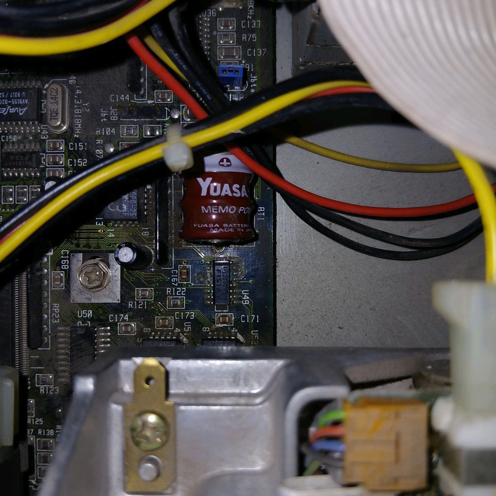
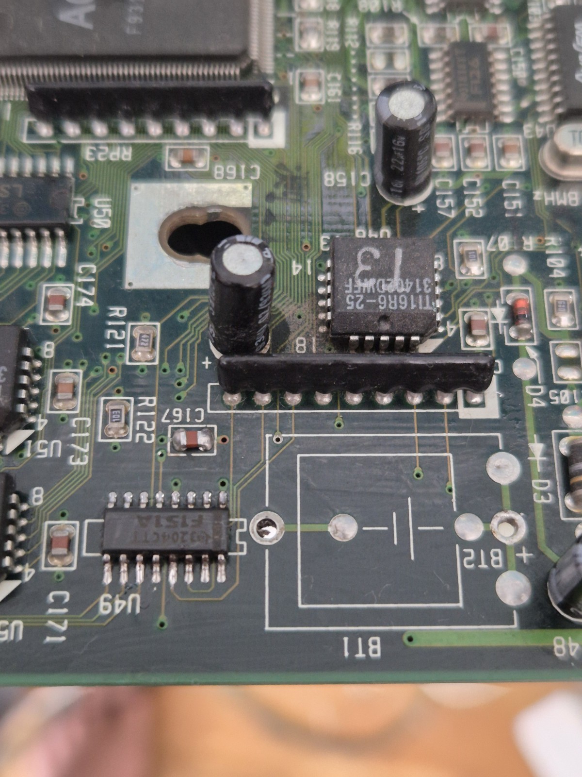
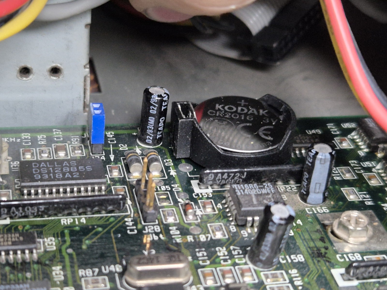
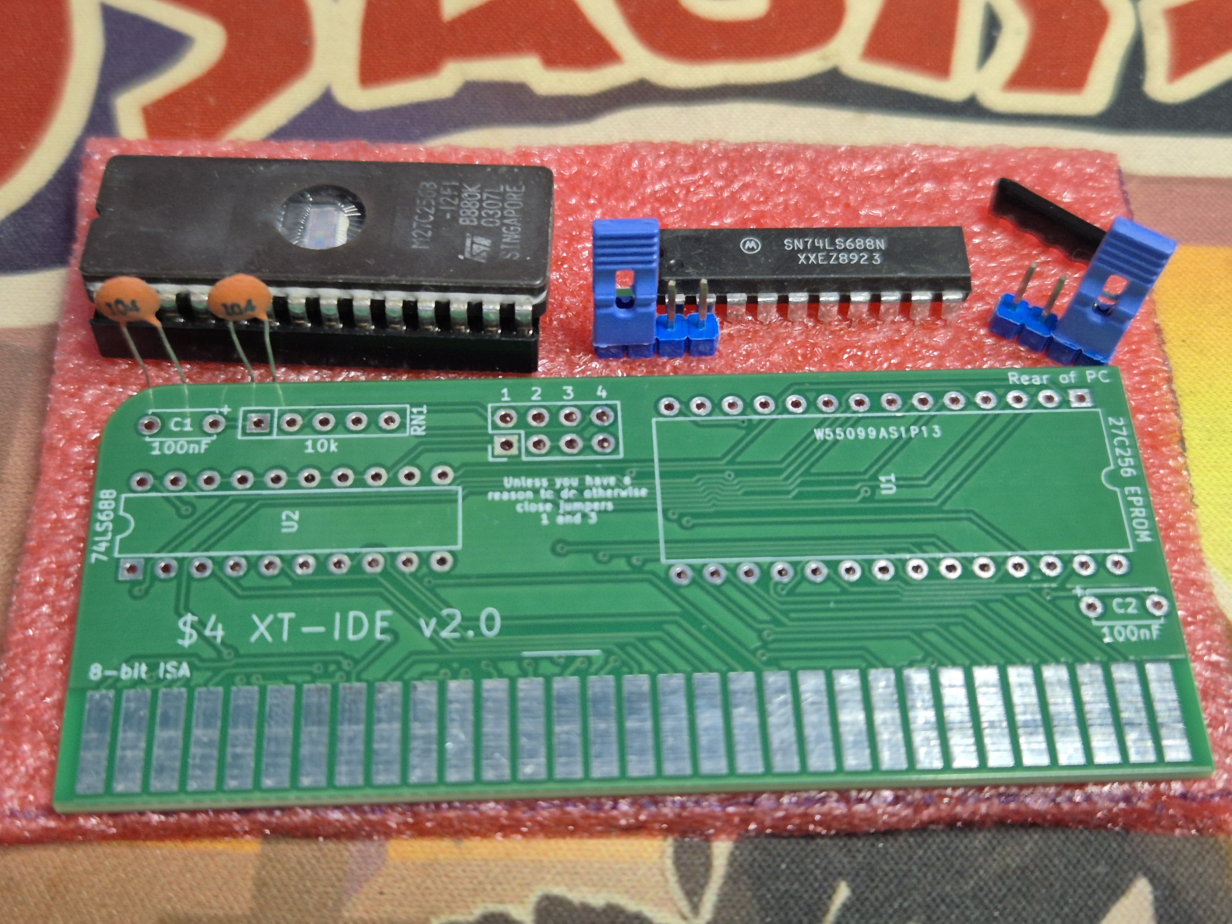
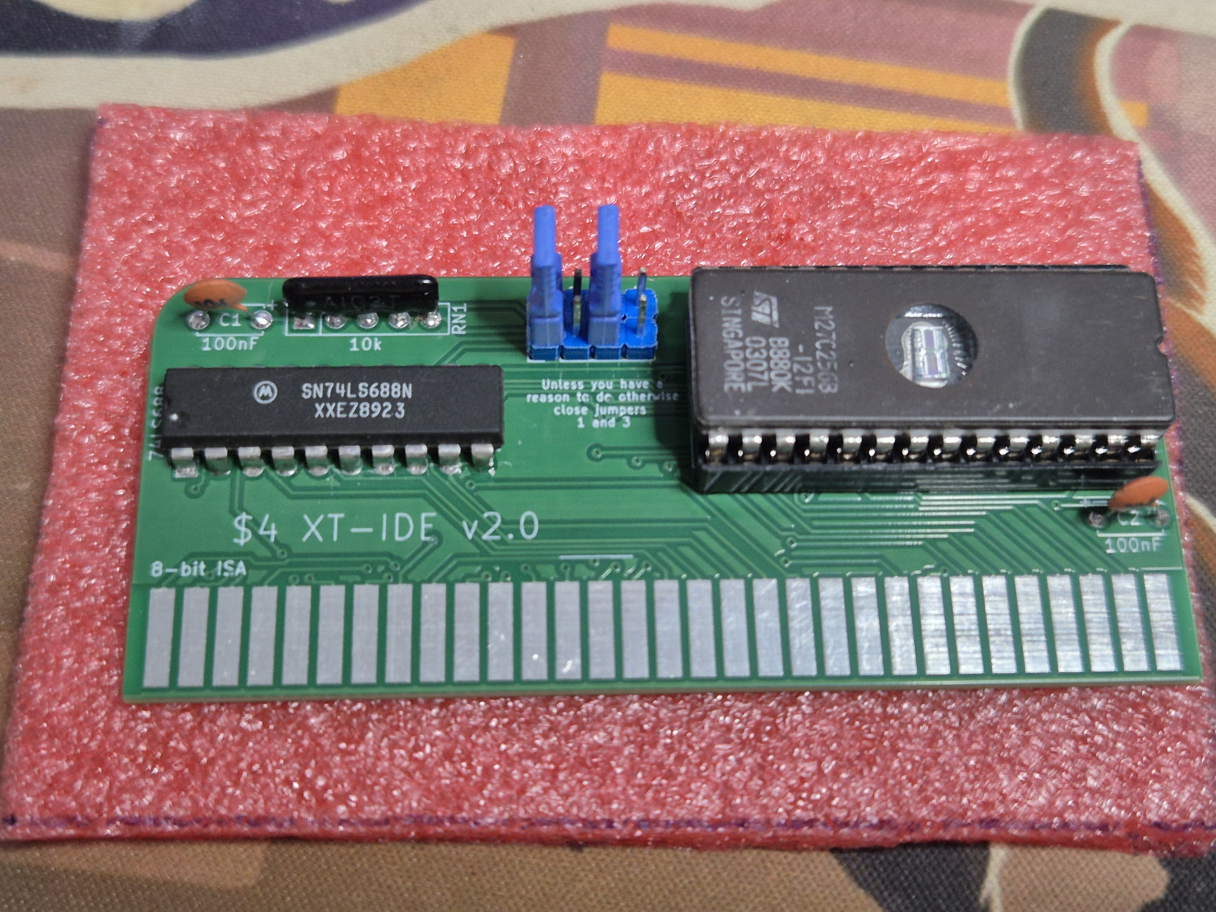
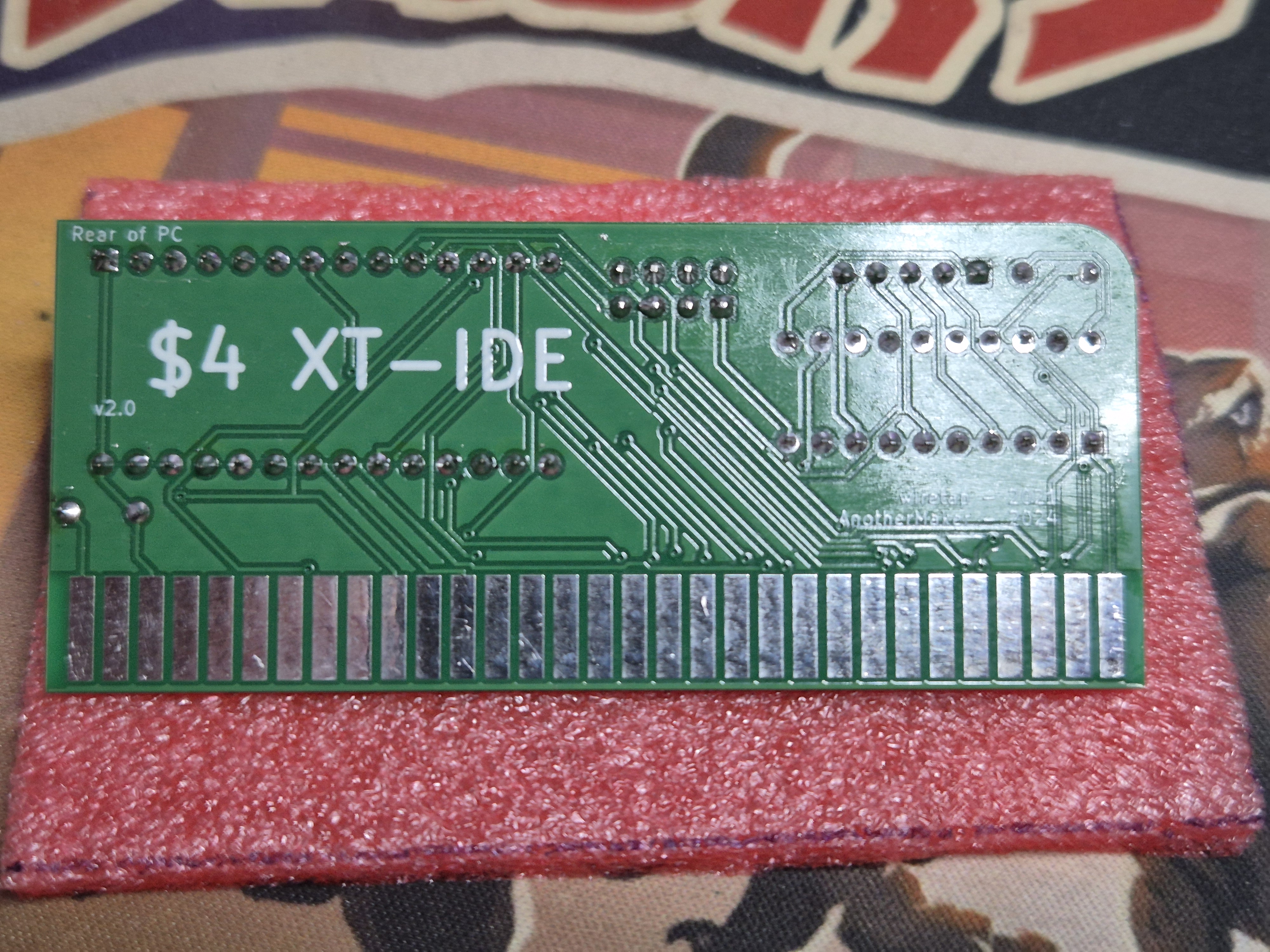
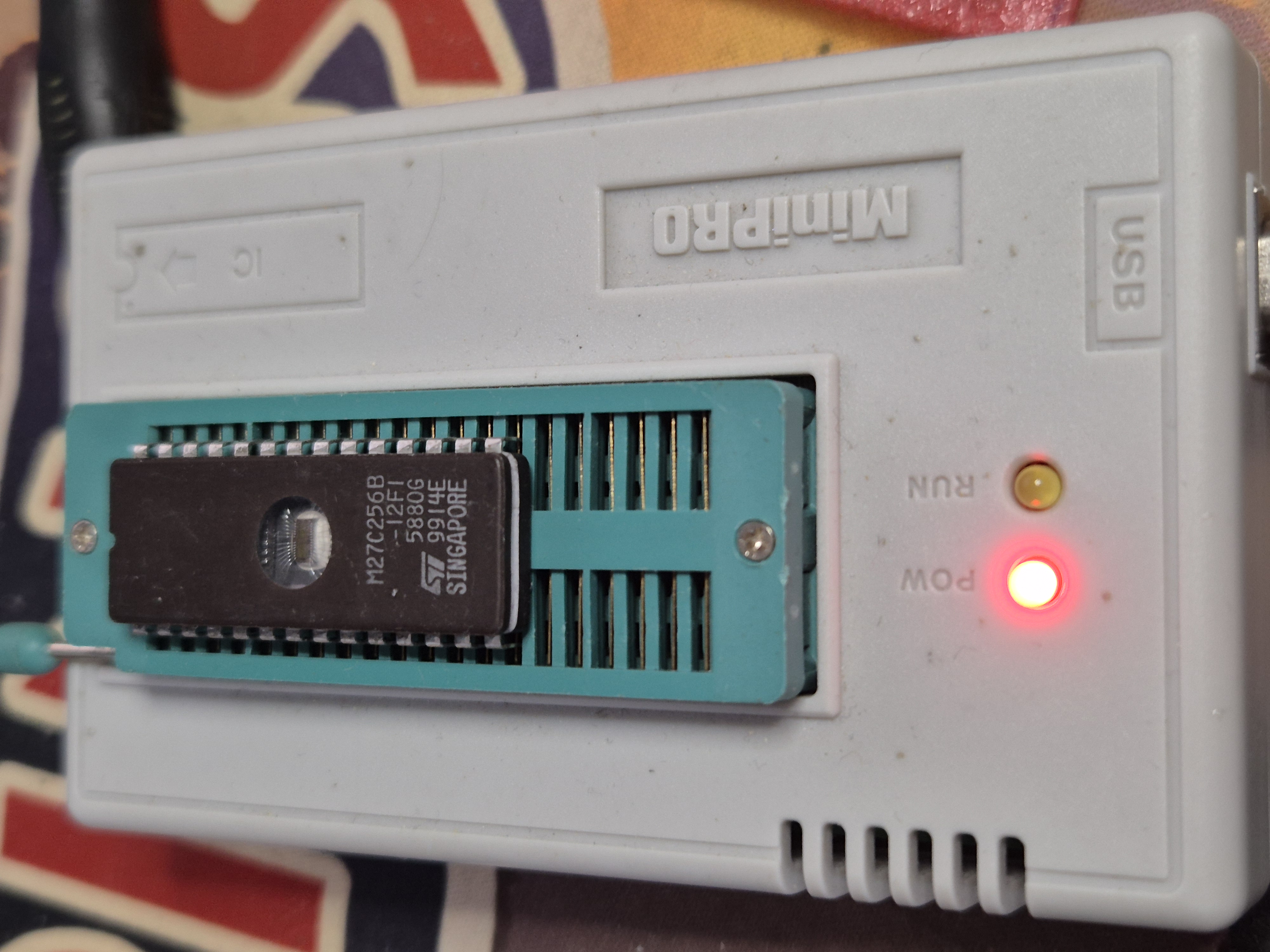
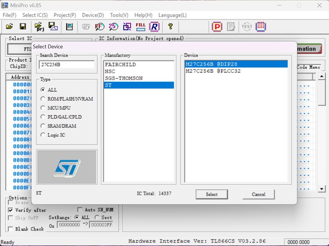
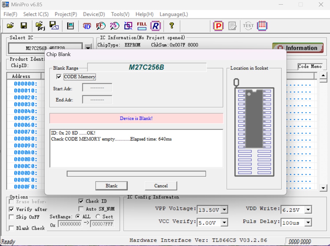
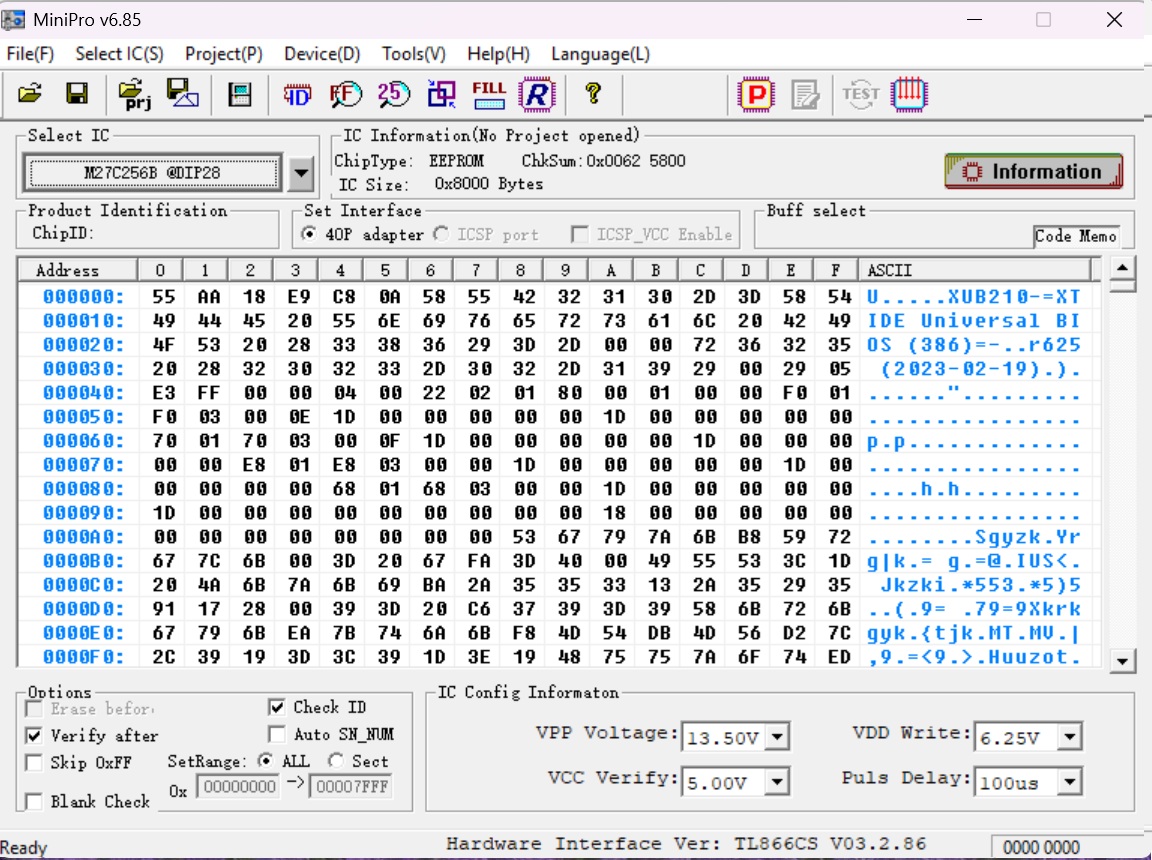
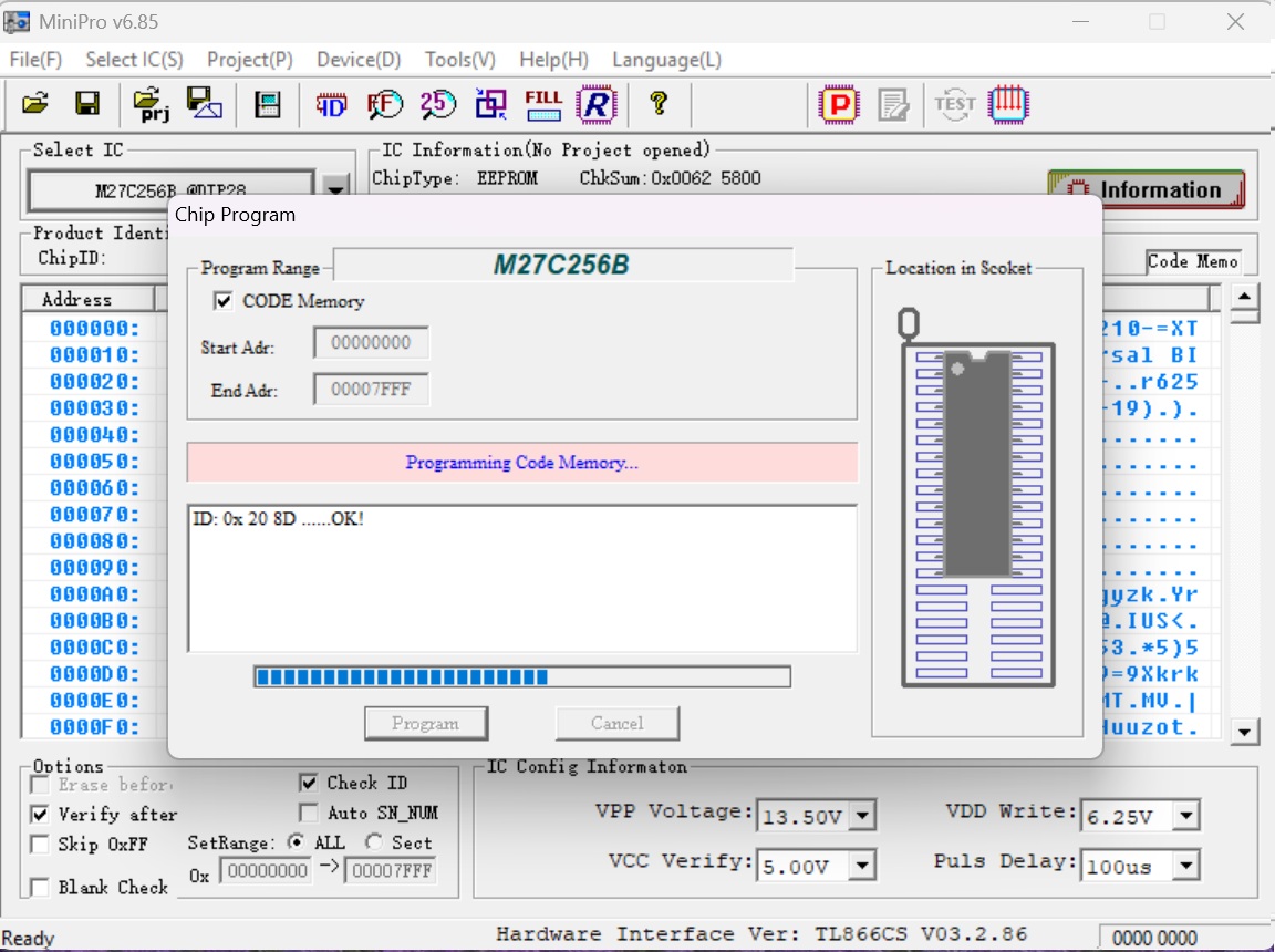
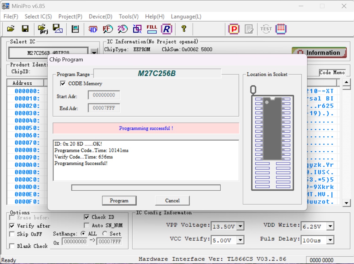
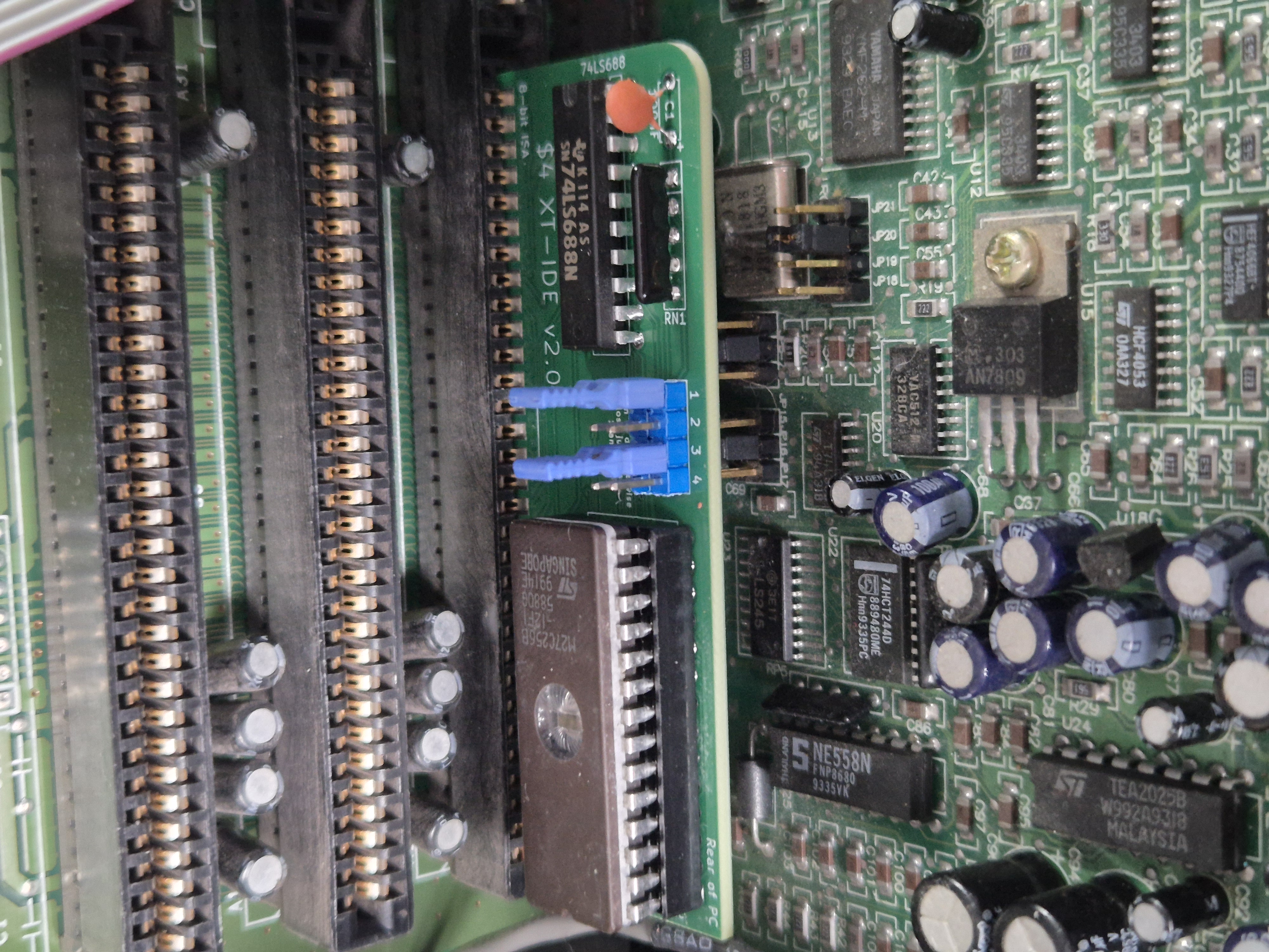
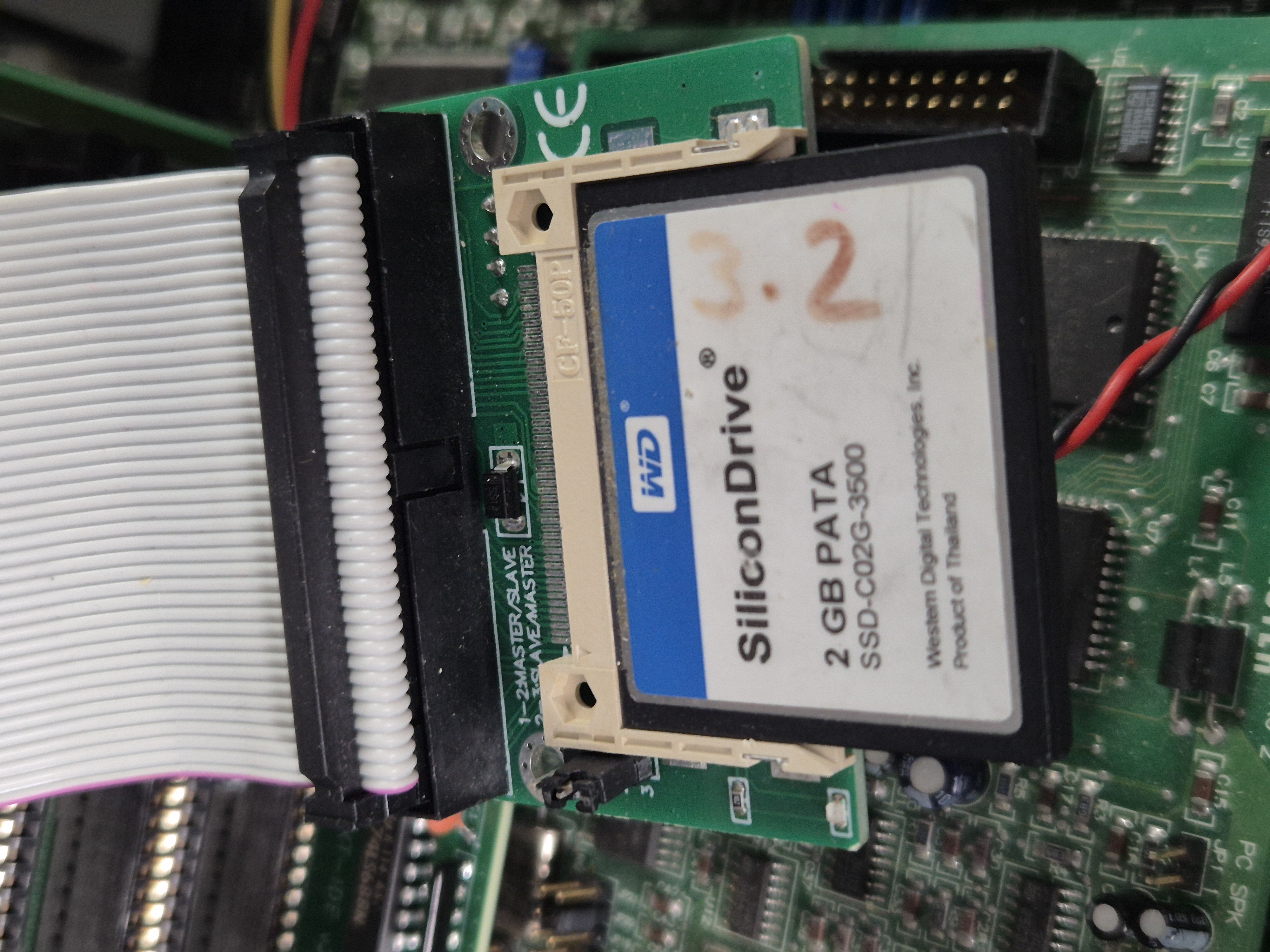
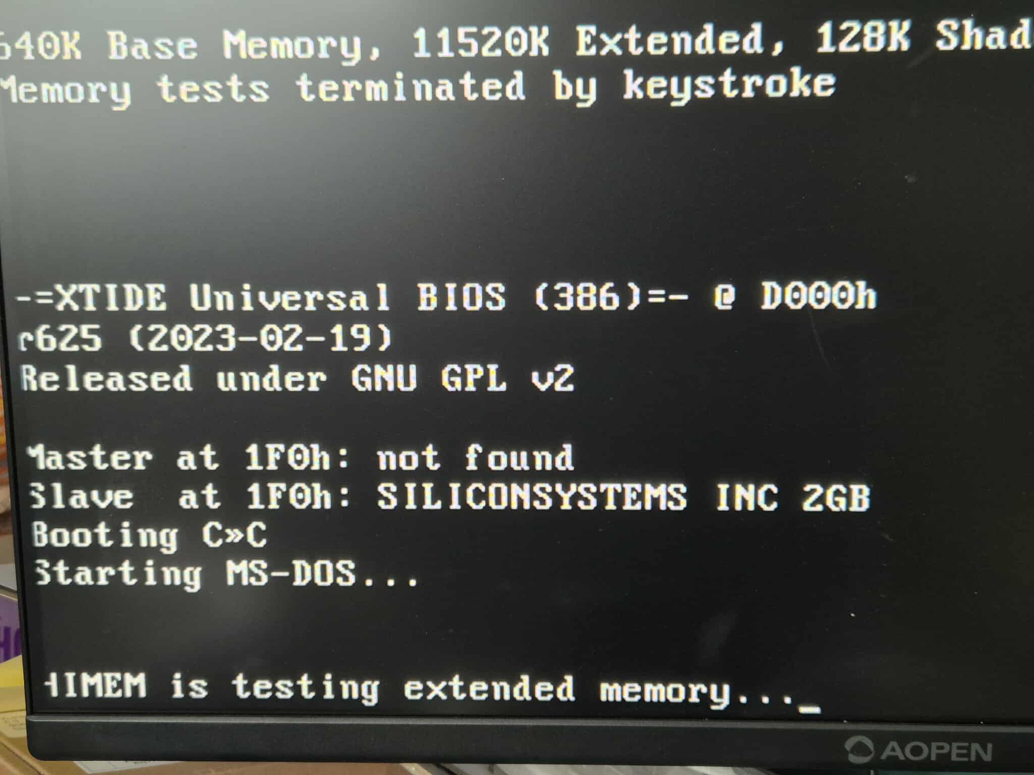
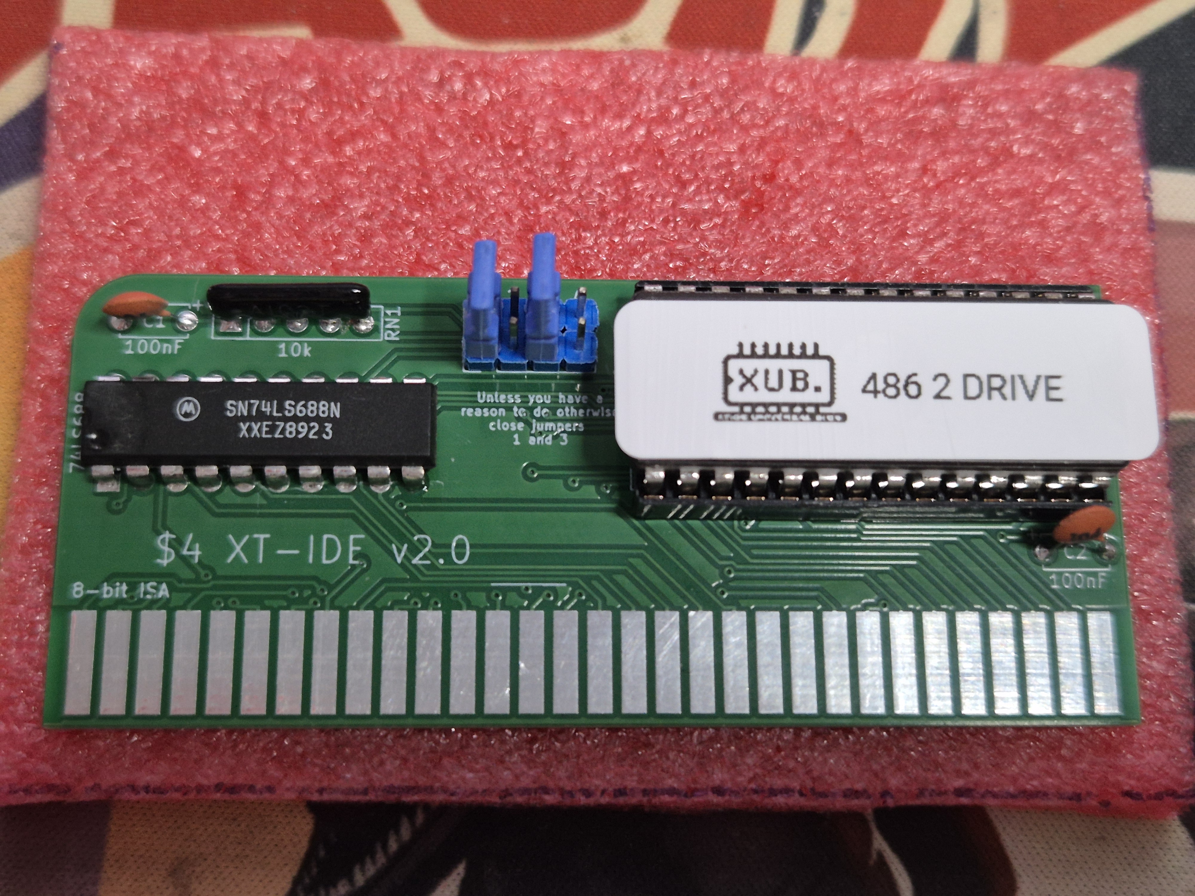
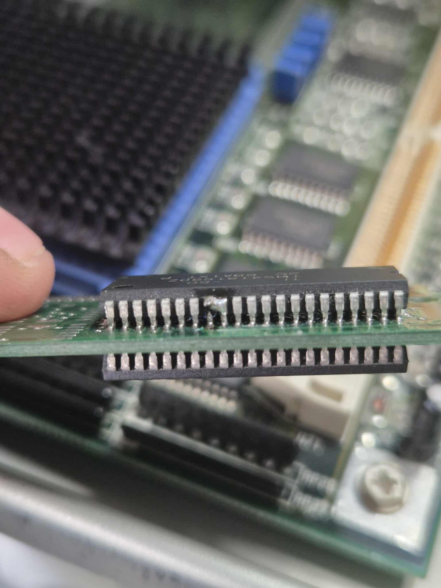
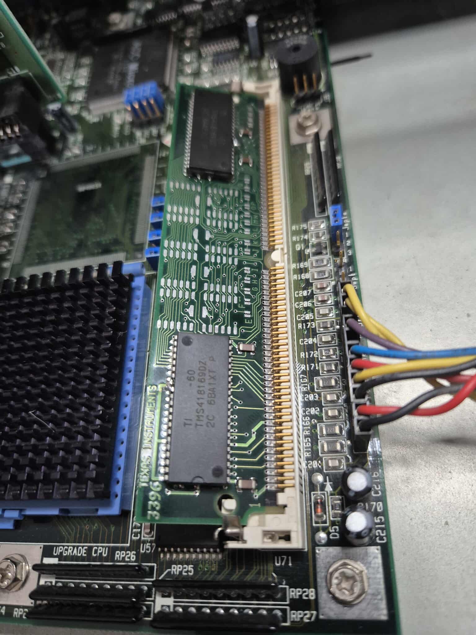
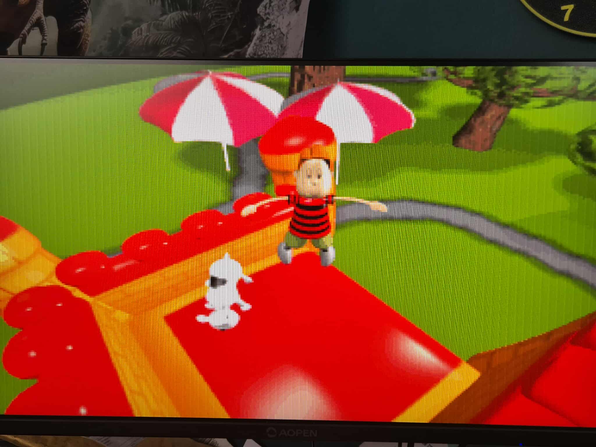
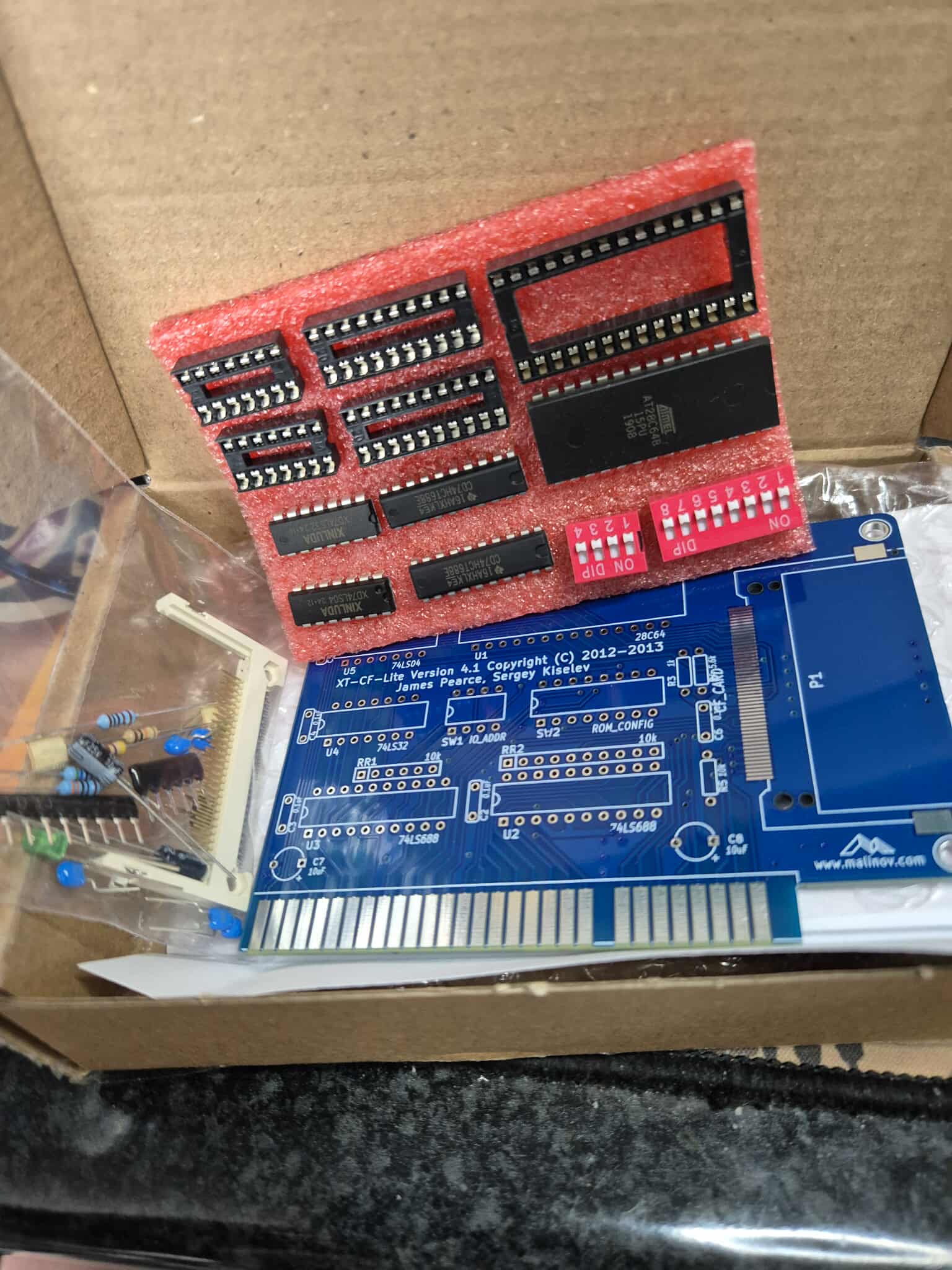
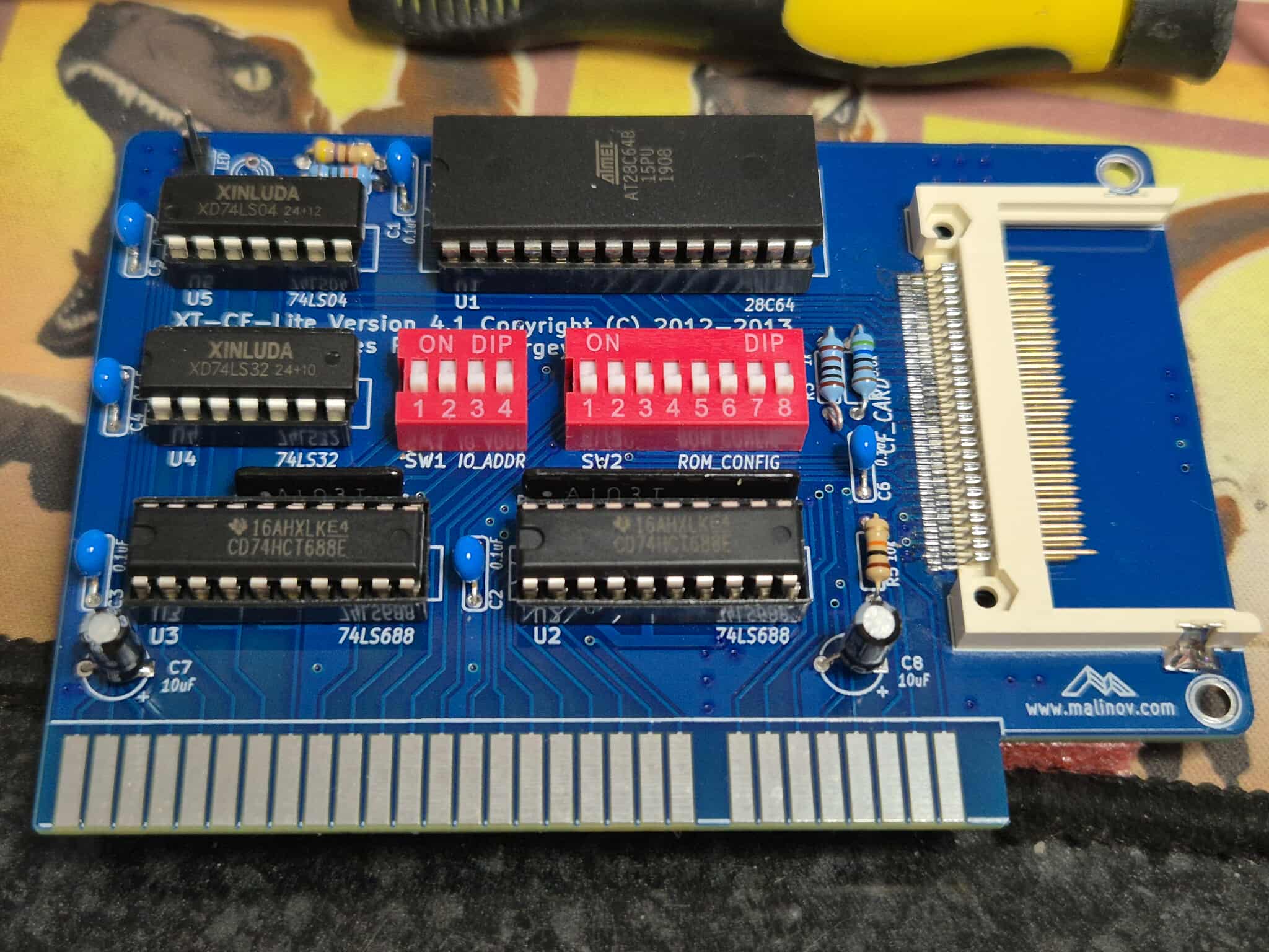
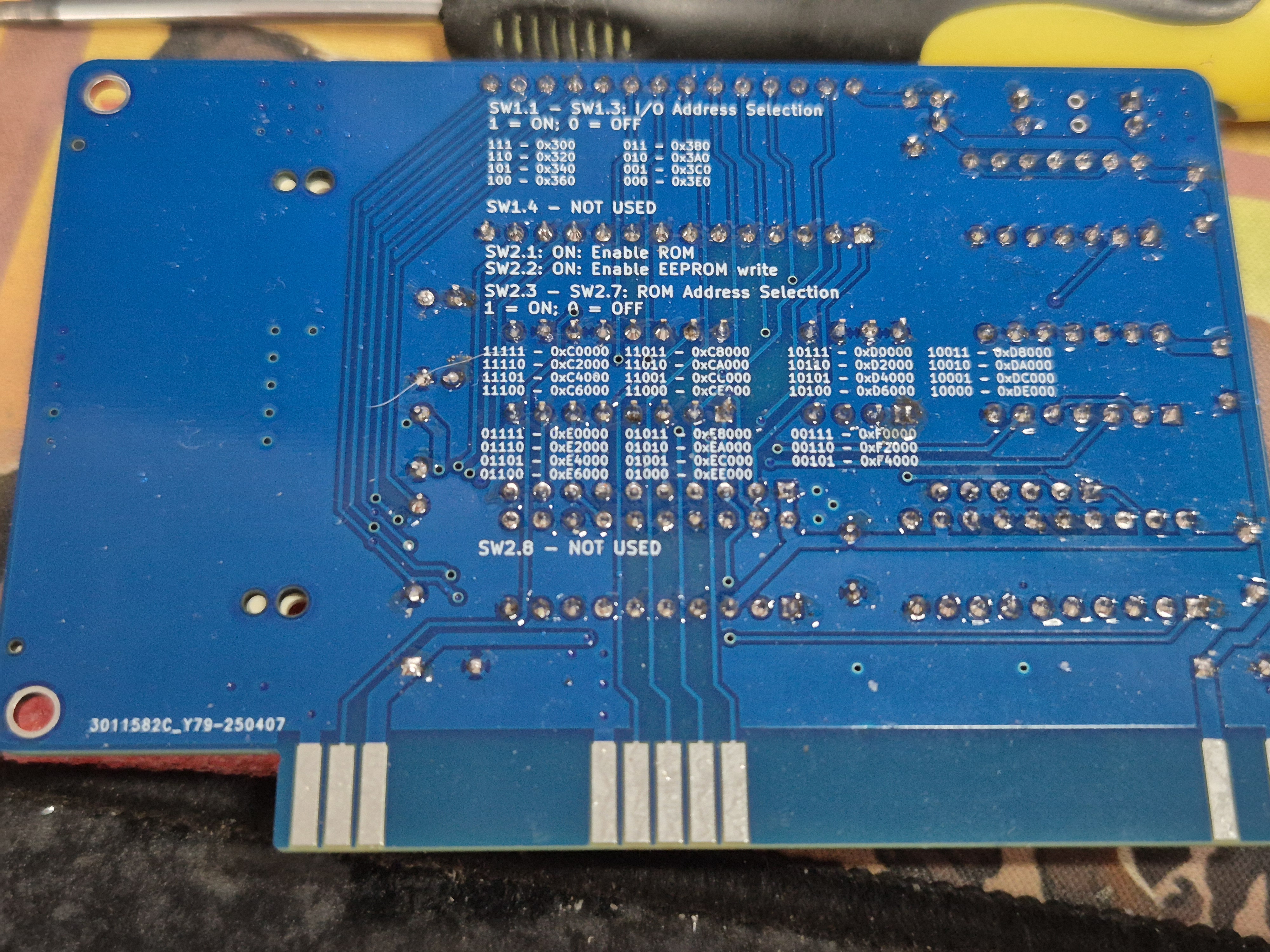
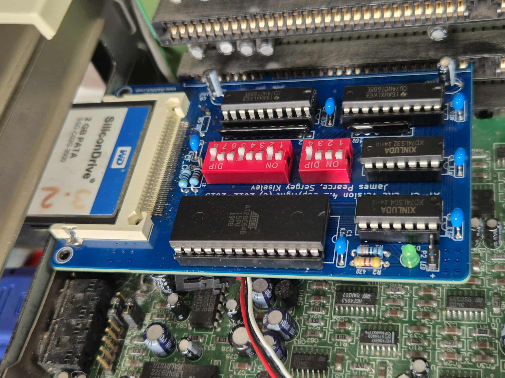
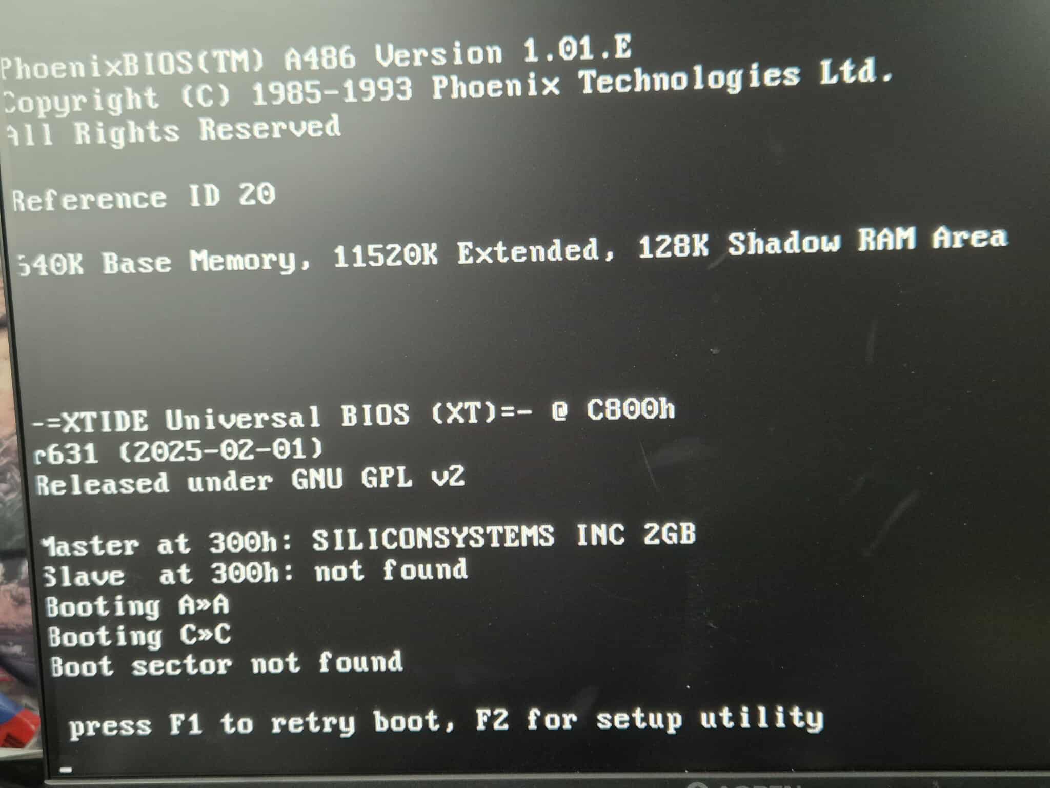
I recently bought a Packard Bell 486 PC. It came with a tape drive, dual floppy drives in 3.5" and 5.25", 4mb onboard ram and a 250mb hard disk drive. I pulled out the tape drive, 5.25" floppy and replaced the 3.5" floppy with a gotek drive. I have also installed an optical drive in one of the 5.25" bays.It had a little bit of battery corrosion but that will be dealt with.First off i de-soldered the original battery and the F151A chip beside it and gave the area a good clean.I then installed a coin cell battery holder and cut the trace to the positive terminal on the underside of the board adding a small diode inline to stop the motherboard from trying to recharge the replacement CR2032 battery.With the battery situation remedied it was time to turn our attention to the HDD. This particular BIOS has a maximum limit of 800MB so I needed to do something about that. Lets build an XTIDE Board. This small board is a bios extension that can take over control of the HDD thereby bypassing the BIOS limitation. I came across a shared project on PCB Way called the $4 XTIDE and decided to have some boards fabricated. I also purchased the rest of the components and waited. After a week or two all the required parts had arrived. So now i have a PCB, 74LS688 logic chip, 10k resistor pack, 2x 10⁴ ceramic caps, a couple of pin headers with jumpers and a 27C256B eprom.It doesn't take too long to assemble :)And the backNow some XTIDE boards can be programmed onboard but this cheap version can not so i need to program the eprom externally. Out comes the TL866 Minipro programmer.Selecting the correct chip.I like to do a blank check first as the eproms are never usually new so there's always a chance it isn't blank and will need erasing. Luckily this wasn't the case with this particular eprom.With the chip confirmed blank I open up the bin file requiredAnd proceed to programmingProgramming complete and verified.Time to install and see if it worksI grabbed an IDE-CF adapter and a 2GB CF cardYay! XTIDE is working and the 2GB card is detected, albeit as a slave device so I'll need to change the jumper on the CF adapter.Now I know its working I need to cover the window on the chip so i printed out a small labelNext up i turned my attention to that 4MB onboard ram. This particular motherboard only has one ram socket and I had a couple of 72 pin simms laying around but none of them would work. The machine just wouldn't post at all when they were installed. I found out that the simms i had were EDO ram and my motherboard would only accept FPM. Now i was faced with purchasing an FPM simm but then i came across a YouTube video that claimed you could convert an EDO simm to work as FPM. Intrigued i took a look. The basic outcome is that you need to cut the OE pin and tie it to the CAS line. Luckily they are right beside each other so this was a fairly easy task. Please take a look at the video which goes into a lot more detail and is fascinating. Having performed the required surgery i installed the simm and the computer sprang to life now with 12MB, 4MB onboard and 8MB simm, of ram.With this new huge amount of ram i was able to install and fire up one of my favourite games. Bullfrog's 1994 classic management sim Theme ParkUpdate... I've had the machine a couple of weeks now and its been working great but one thing i was a little disappointed with is that the motherboard only had a single IDE onboard which meant i had to use the HDD as master with my optical drive as a slave. I decided to remedy this with a better XTIDE solution. One with built in CF adapter. This kit cost me about £35 including shipping to the UK from Slovakia. It came as a kit and required assembly although the eeprom was pre-programmed by the seller.Assembly didn't take long to complete and was a fun project to complete.The back shows how to configure the cards dip switches.I moved the 2GB CF over from the CF-IDE adapter, setting the optical drive to master on its own cable and proceeded to boot.This new board found the drive but for some reason wouldn't boot into DOS. Not a huge problem, i had previously replaced the ageing floppy drive with a gotek drive so i reinstalled DOS 6.22, installed drivers for mouse, cdrom and my Sound Blaster Pro II and all went beautifully. The PC didn't come with the key for the keyboard lock on the front so i'd like to see if i can replace that at some point just because i can. I then need to fully reassemble the PC and take some new photos because its in a state i'm happy with now. I have a Packard Bell CRT monitor that i will pair with it and using a KVM it will share the monitor, mouse and keyboard with my other Packard Bell PC, the Pentium III with onboard Voodoo III but that's a story for another article.....